
FEEDBACK CONTROL OF RF PLASMA PROCESSING REACTORS*
Shahid Rauf and
Mark J. Kushner
Department of Electrical & Computer Engineering
University of Illinois at Urbana-Champaign
1406 W. Green St., Urbana, IL 61801
1. Introduction
As microelectronics device feature sizes continue to shrink and wafers continue to increase in size, it is becoming necessary to have tighter tolerances during the fabrication process. This is particularly true for plasma processing steps. Feedback control has, therefore, become an important issue in plasma processing equipment design. Comprehensive plasma equipment models linked to controller algorithms would greatly aid in the investigation and optimal selection of control strategies. To address this need, we have recently developed a numerical plasma equipment tool, the Virtual Plasma Equipment Model (VPEM). It has been used to investigate a number of problems in which response surface based controllers were used to compensate for actuator drifts, nullify the effect of external disturbances and improve important process parameters such as etch uniformity. We are presently concentrating on controller design improvements, experimental validation and advanced techniques for polysilicon etching using Cl2.
2. Computational Tool
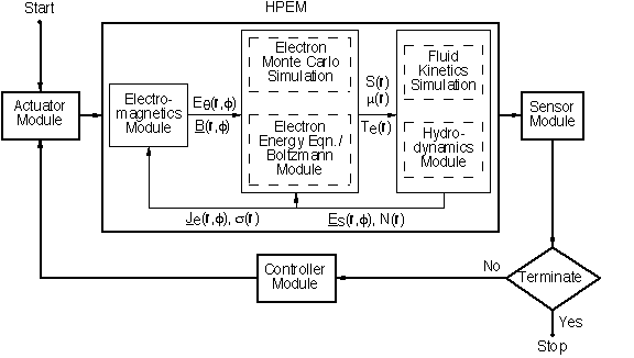
The VPEM is an extension of the Hybrid Plasma Equipment Model (HPEM), a detailed plasma equipment simulation tool. To make the HPEM suitable for studying issues related to feedback control, we added sensor, actuator and programmable controller modules. The sensor module emulates measurements of experimental sensors. Some of the implemented sensors (and their experimental analogues) are spatially averaged densities (optical emission spectroscopy), ion flux to surfaces (ion energy analyzer) and plasma density (Langmuir probes). The actuator module changes process parameters that can be externally controlled in experiments, such as inductively coupled power, applied voltage on electrodes, gas pressure, flow rate and mole fraction of gases in the feed. As shown below, The sensor module, actuator module and the HPEM are linked together in a feedback control loop through a programmable controller module.

Fig. 1: A schematic of the Virtual Plasma Equipment Model (VPEM).
In the problems that have been investigated using the VPEM, the controllers have been designed primarily using a response surface based methodology. The design procedure consisted of constructing the response surfaces over the actuator range of interest, fitting a polynomial to these response surfaces, and using their coefficients to develop a linearized model for system response. In practice, these controllers were found to be fairly robust against drifts in actuators and external disturbances.
3. Results
A number of feedback control related problems have been studied using the VPEM in inductively coupled plasma (ICP) and reactive ion etching (RIE) reactors. We considered Ar, Ar/N2 and Ar/Cl2 gas mixtures. In ICP reactors, the sensors we used were spatially averaged species density and ion flux to wafer. The actuators included inductive power, pressure and rf voltage on the bias electrode. It was found that one and two variable controllers were able to compensate for perturbations caused by small gas leaks and modification in reactor surface, and control up to 20% drifts in actuators. In the RIE reactor, we demonstrated the capability of designing controllers by investigating a technique for improving the uniformity of wafer-impinging ion energy flux. In this technique, the powered electrode of the RIE reactor was split into two, and the voltage on the two segments is controlled independently. Some results from these studies were recently published in the IEEE Transactions on Semiconductor Manufacturing. Another paper that discusses model validation, controller design improvements and control strategies is currently under preparation.

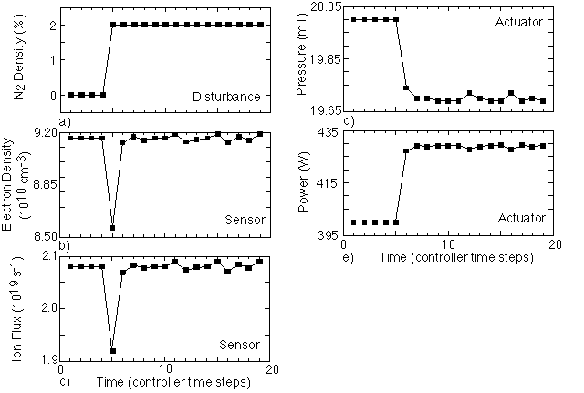
Fig. 2: The sensor, actuator and disturbance time history.
In the results shown above, we have plotted the sensor, actuator and disturbance time history for a control problem. The simulations were done in an ICP reactor with Argon. The sensors included spatially averaged electron density and total flux of ions to the wafer. The actuators were gas pressure and inductively coupled power. The controller is designed to maintain the sensor signals at preset values. In the simulations, we start out with a given power and pressure. At T=5, 2% N2 is suddenly introduced into the reactor to emulate an air leak. Since some of the power gets diverted to non-ionizing excitation collisions of N2, the electron density and ion flux decreases. When the controller sees this change in sensor signals, it adjusts the actuators to compensate for this change. This brings the sensor signals back to their original values.
*This work is sponsored by Defense Advanced Projects Research Agency and Air Force Office of Scientific Research
Last updated: September 30, 1998.